Creating a diagram of a progressive cavity pump is essential for understanding its design and functionality. This type of pump is widely used in various industries for its ability to handle viscous fluids and provide a steady flow. In this article, we will guide you through the steps to create a clear and informative progressive cavity pump diagram.
Understanding the Components
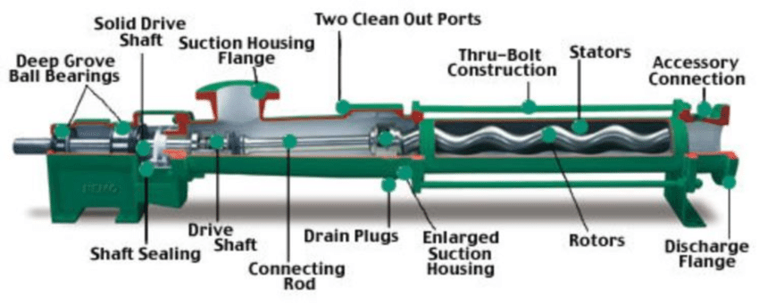
Before diving into the diagram creation, it’s crucial to familiarize yourself with the main components of a progressive cavity pump. Here are the key parts you should include:
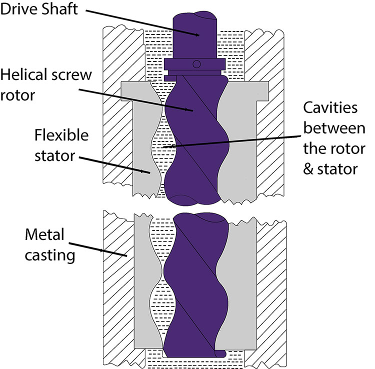
- Rotor: The helical screw that rotates within the stator, creating a cavity for fluid movement.
- Stator: The stationary part that surrounds the rotor and has a helical shape, forming a seal with the rotor.
- Drive Shaft: The component that connects the rotor to the motor, allowing for rotation.
- Inlet: The entry point for the fluid to enter the pump.
- Outlet: The exit point for the fluid after it has been pumped.
- Support Frame: The structure that holds the pump components in place.
Steps to Create the Diagram
Creating a progressive cavity pump diagram involves several steps. Follow these guidelines to ensure clarity and accuracy in your illustration.
Step 1: Gather Materials
You will need the following materials:
- Drawing software or a sketch pad
- Ruler or straight edge
- Pencil and eraser (if sketching by hand)
- Reference images of progressive cavity pumps
Step 2: Sketch the Basic Shape
Start by sketching the overall shape of the pump. Typically, the rotor is depicted as a long, helical line, while the stator is shown as a surrounding cylindrical shape. Make sure to leave enough space for other components.
Step 3: Add Key Components
Once the basic shape is established, add the key components:
- Draw the Rotor: Use a helical line to represent the rotor inside the stator.
- Outline the Stator: Show the stator as a larger cylinder that encompasses the rotor.
- Indicate the Drive Shaft: Draw a line extending from the rotor to represent the drive shaft.
- Mark the Inlet and Outlet: Clearly label where the fluid enters and exits the pump.
Step 4: Label the Components
After you’ve added all the components, label each part clearly. Use arrows or lines to connect the labels to the corresponding components. Ensure the text is legible and concise.
Step 5: Review and Refine
Take a step back and review your diagram. Check for accuracy and clarity. Make any necessary adjustments to improve the overall presentation. If using software, utilize tools for alignment and spacing to enhance the diagram.
Conclusion
Creating a progressive cavity pump diagram is a valuable exercise that aids in understanding the pump’s operation and structure. By following the outlined steps and focusing on the key components, you can produce a clear and informative illustration. Whether for educational purposes or engineering design, a well-crafted diagram serves as a vital tool for communication and understanding in the field of fluid mechanics.