In the case of long-selling and series models, there are many examples of late models and series models that have been enhanced and updated with various parts compared to early models. If it is possible to achieve a fuller driving experience with little change in appearance, it should be possible to enjoy fuller customization using the factory parts in such a way.
Here, we would like to report on an actual example of an attempt to strengthen and enhance the power generation system and charge control system at the same time.
- Focus on improvements because it is a long seller
- Late models and further evolutionary models
- Machining of the fastening part to allow physical attachment
- I made new wiring by diverting a set of couplers.
- Confirmation of charging start-up is a basic task
- POINT
Focus on improvements because it is a long seller
Comparison of a stator coil for a later model (left) and a stator coil for an earlier series model (right), in which the number of coil turns was increased by subdividing the coil core (iron core) to achieve a more stable 3-phase AC power generation. Although the factory component on the right should be sufficient in terms of power generation output, strengthening the generator should be considered essential when the performance is not as per the original technical data due to aging deterioration, or when aiming for stabilization when installing electrical custom parts.
Late models and further evolutionary models
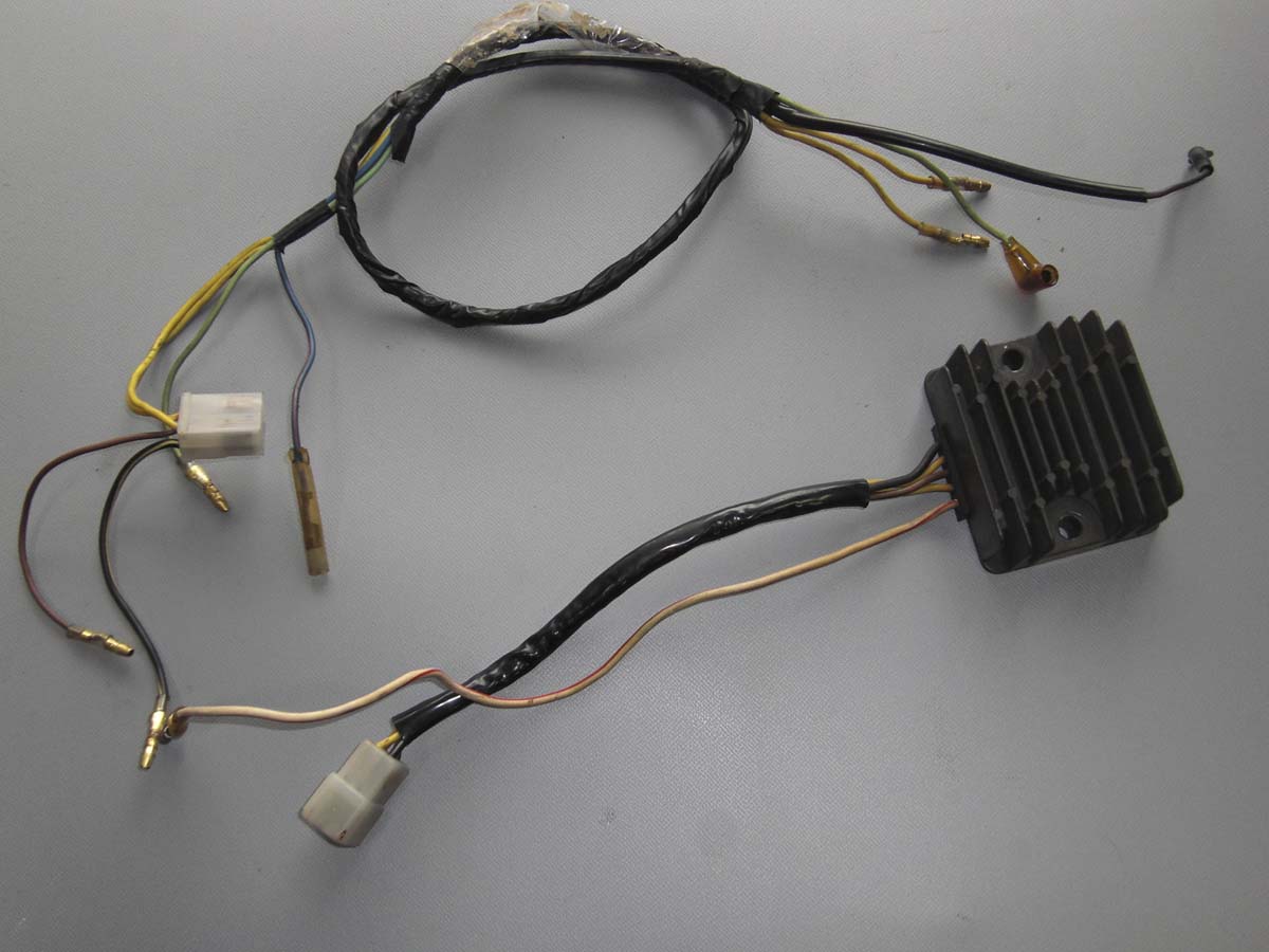
OEM regulator rectifier and sub-harness for Kawasaki KZ550. Since the alternator has two rising wires, it is equipped with a regulator rectifier that matches its specifications.
For example, if it is a domestic spec model, it seems to be common parts with E1 to E3 of Z400FX. The OEM regulator rectifier of Kawasaki (model unknown, but GPZ750 series!?) that was stocked in the garage at home was used. I decided to use the regulator rectifier Kawasaki stocked in my garage. The stator coil was replaced with a 3-output type for the later model, so I needed a regulator rectifier for the same type.
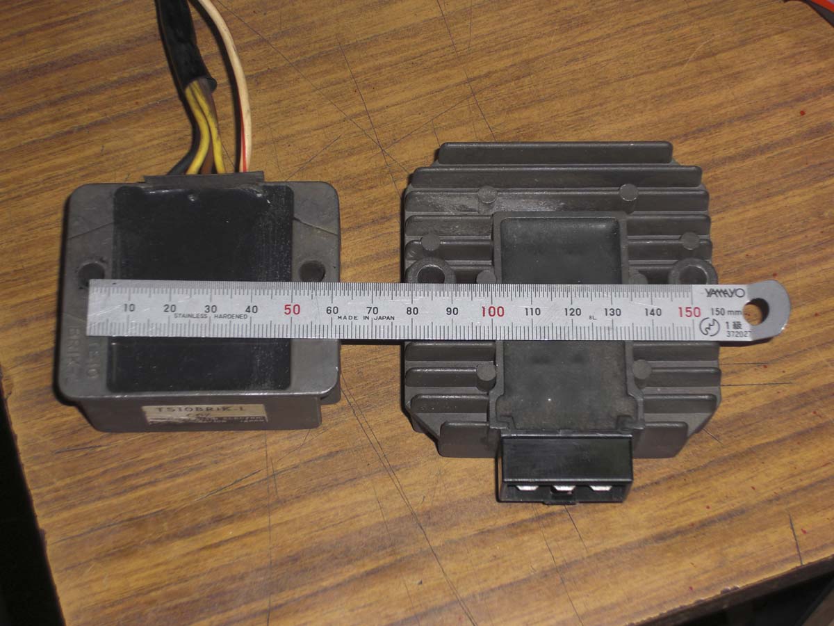
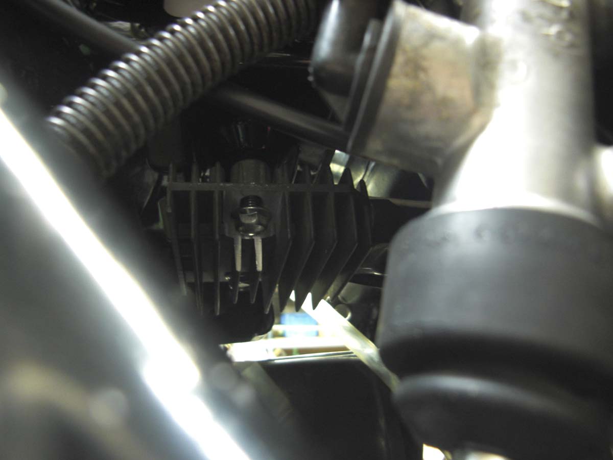
Machining of the fastening part to allow physical attachment
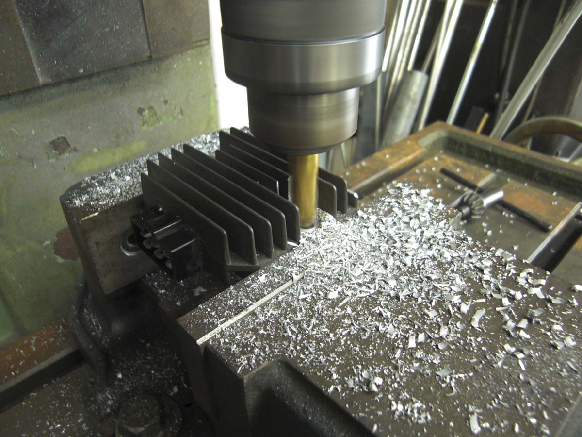
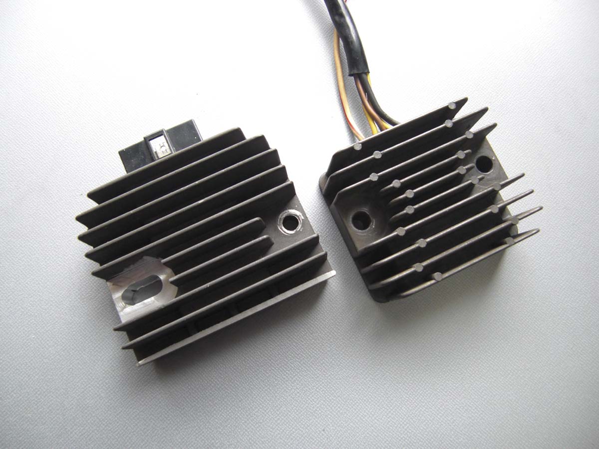
In order to match the mounting pitch of the regulator rectifier body with the mounting space requirements, the body fastening area was machined with a long hole. This processing made it possible to bolt on to the KZ550 chassis. While the regulator rectifier body and the integrated harness are of the harness type, the modified regulator rectifier uses a coupler connector for connection. This type was used in the late GPz and Zephyr series.
I made new wiring by diverting a set of couplers.
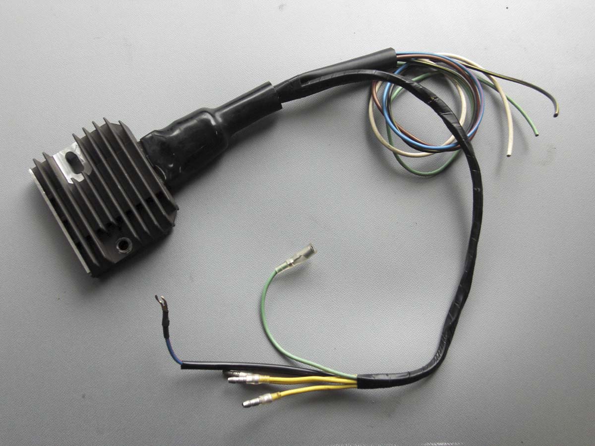
Prepare a coupler that matches the connector on the regulator rectifier.
When removing parts from a disassembled vehicle during OEM diversion practices, for example, it is sometimes easier to divert the wiring around the coupler to make wiring easier later on. Using the wiring diagram as a reference, we fabricated a special harness using the same color harness code as Kawasaki’s.
Confirmation of charging start-up is a basic task
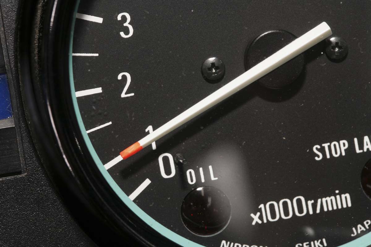
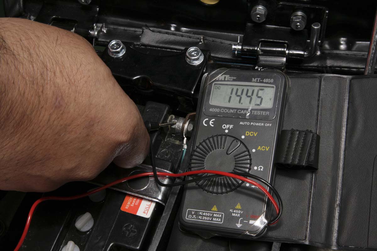
After installing the parts and making the wiring connections & routing, let’s first check the battery terminal voltage situation. When the engine is stopped, the voltage is around 12.4 volts, and when the engine is idling to start, the voltage is around 12.5 volts. Let’s also measure the battery voltage when idling with the headlights on and at higher engine speeds. Know that the numerical data may vary depending on the battery condition.
POINT
Point 2 – Surprisingly easy to remodel and improve electrical systems
Point 3 – Thoroughly check the function after replacing parts.
At the same time as purchasing the export-spec KZ550, we compared the electrical systems of the Z400FX, Z400GP, and GPz400F series, the domestic middle-four series, by referring to their service manuals. According to an experienced mechanic who knows the middle-four series well, the electrical system of Z400FX, especially from the first generation E1 to E3, often had to charge failure even in the environment at the time of its release. The specific symptom is the so-called “battery up”. When a problem occurs, it is logical to suspect the regulator rectifier, but as a conclusion, there were many cases where the alternator itself had low output without any problem.
The last model, the E4, has a countermeasure component, which has reduced the number of problems with battery drain. The difference between the early series and E4 is in the alternator specifications. The Z400FX of the early series is equipped with a 2-wire AC alternator as standard, while the E4 uses a 3-wire 3-phase AC generator. Incidentally, many European specification models (with headlight switches) use the same 2-wire output as domestic E1 to E3.
On the other hand, in the case of the KZ400J and KZ550 series for North American specifications (U.S. specifications), road traffic law requires the headlights to be on at all times.
Considering such a situation, the North American specifications have adopted 3-phase AC power generation from the time they were new. It was the opinion of a veteran mechanic who knew the Kawasaki Middle Four well that simply changing from a 2-AC output system to a 3-phase AC system would improve the battery charging situation. Of course, the regulator rectifier would have to be replaced with a compatible component to accommodate the change in specifications, but this measure would ensure that the charging system would be stable.
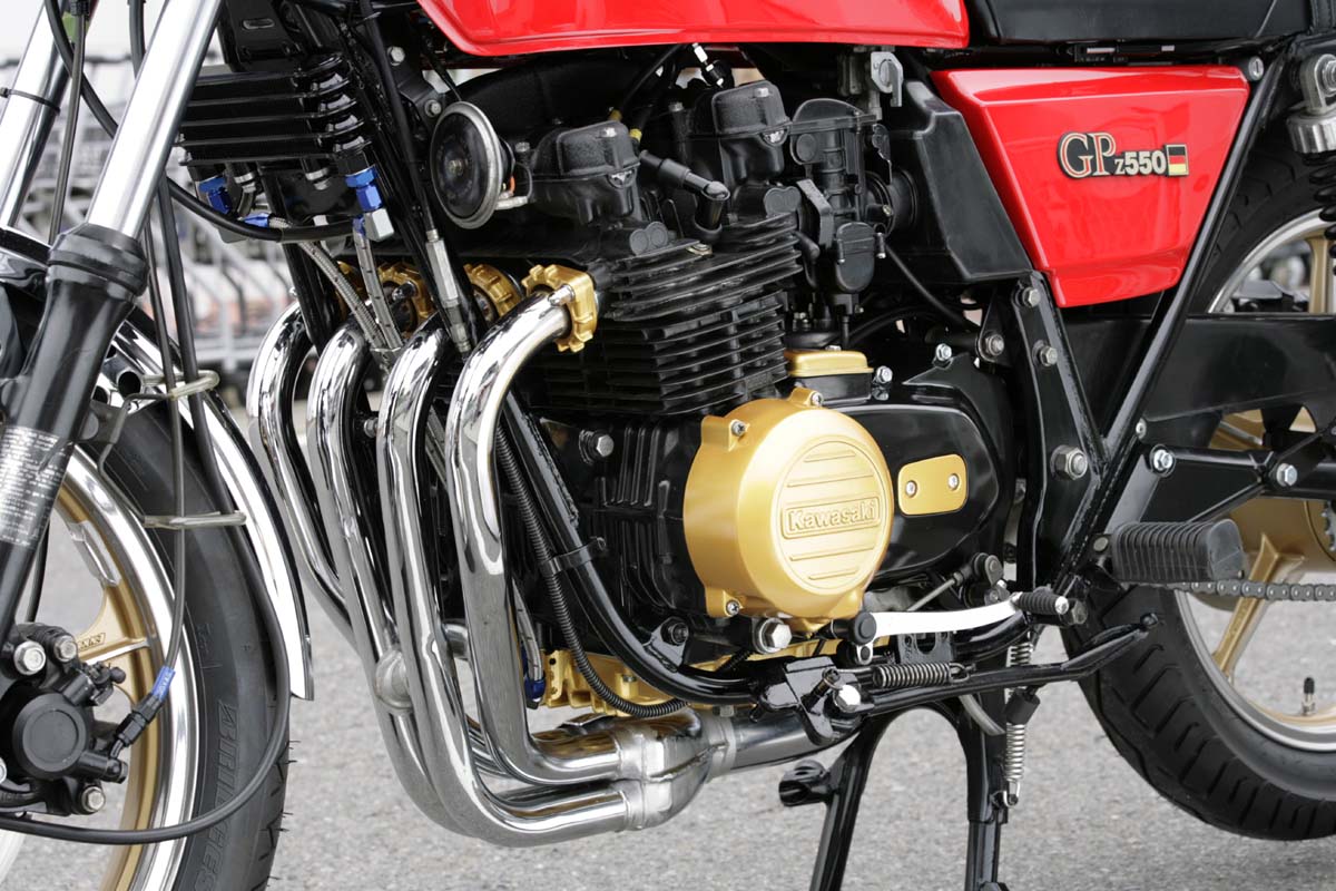
We decided to remove the 2-output KZ550 alternator and install a 3-phase AC alternator (using used parts for a North American KZ550LTD) and a regulator rectifier that we thought would be compatible with the alternator! I decided to install a 3-phase AC alternator and a regulator rectifier that I thought would be compatible with the alternator.